CDL - ISA106
CDL - ISA106
CTRL Designer LLC (CDL) provides a comprehensive step-by-step workflow to implement procedural automation:
- CDL Tools for Excel™: A set of Microsoft Excel program
- ISA106 Implementation Guide: Being published on Amazon
- ISA106 Work Process Implementation: Converting existing company work process
ISA106 Procedures for continuous process operations include situations of start-up, shutdown, abnormal situations, hold step, and transitions of process feed/output. These standard operating procedures (SOP) exist in manual form, probably written, prior to automation. The goals are to increase uniformity and consistency of procedure automation and reduce the risk, cost, and errors associated with automating procedures.
An overview of CLD-APS106 work processes is available here.
The ISA106 work process can be maped to
- Front-end Loading (FEL)
- V-model (GAMP)
Front-end Loading (FEL), also referred to as front-end engineering design (FEED), is the process for conceptual development of projects in processing industries such as upstream oil and gas, petrochemical, natural gas refining, extractive metallurgy, waste-to-energy, and pharmaceuticals. This involves developing sufficient strategic information with which owners can address risk and make decisions to commit resources to maximize the potential for success. The FEL is divided into three stages:
- Front-End Load – Options Study – FEL1
- This answers the question, “what are my options to achieve my project goals?”. For example, in the processing of nickel laterite ore, it might be possible to build either a pyrometallurgical or hydrometallurgical processing plant. This stage would study both options and recommend the best one based on the specific project requirements
- Front-End Load – Feasibility Study – FEL2
- The selected option is developed up to a pre-defined level of detail not yet sufficient for construction and operation, but enough to develop a cost estimate, and a schedule estimate, and to make any critical decisions that will influence the final design of the plant.
- Front-End Load –Front-End Engineering Design – FEL3
- The engineering team will now fully design the plant, including the exact specifications for how it will be constructed, commissioned, started up, and operated. The proposed plant will now have a detailed cost estimate and construction schedule.
V-model: The V-model is a graphical representation of a systems development lifecycle. It is used to produce rigorous development lifecycle models and project management models. The V-model falls into three broad categories, the German V-Modell, a general testing model and the US government standard.
- User Requirements Specification (URS) is a document that defines the purpose and justification of the procedural automation that the user plans to build (or modify). It provides specific, measureable performance criteria. The URS is not “How to do” document but :What to do” document.
- Functional Requirements Specification (FRS) is a document that describes what the end-users want the control system to do to satify the URS requirements. It is NOT how the control system works. It includes input/output (IO), Step/Transitions definition, IO allocation to CM and CCM Libraries. It is a document that specifies the functionality of an implemented control system.
- Detailed Design Specification (DDS) is a collection of CM and CCM and their associated IO and parameters to be used as part of the implementation. The DDS contains all information required to build the control system based on FRS.
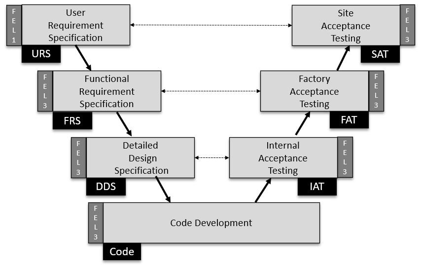
V-Mode and its relationship with FEL
A detail V-Model that is being used by the CDL tools for Excel(TM) is shown below:
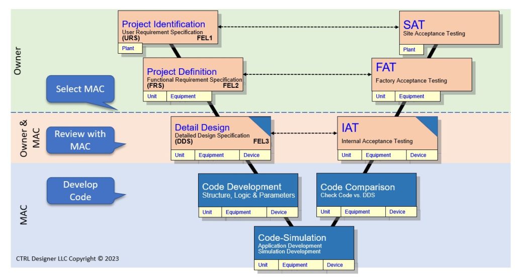
CDL tools and workflow provides:
- Front-End Load – Options Study – FEL1:
- Development of performance baseline for existing plants utilizing Industrial Plant Assessment ™ (IPA).
- Front-End Load – Feasibility Study – FEL2:
- Review ISA106 Physical Model definition.
- Develop the Plant Physical Model (PM).
- Review of Standard Operating Procedure (SOP) and P&ID.
- Divide the plant module (PM) into its associated Physical Unit Models (UM) and Physical Equipment Models (EM).
- Develop Operating Trends (OT) for PM/UM using Operating Trends for Excel™.
- Define the Mode of Operations (MofO) for each unit (UM).
- Develop User Requirement Specification (URS) in the CDL Tools ™ package.
- Import all plant module (PM) tags.
- Allocate Tags to Units (UM).
- Define unit type as
- stand-alone (UM is defined and used once)
- master (UM is defined and re-used), and
- reused or copy (The Master UM is IO is replaced)
- Generate the Functional Requirement Specification (FRS) files.
- Review CDL Generic Control Module (CM) Library and develop the User Control Module (CM) Library.
- Review CDL Generic Complex Control Module (CCM) Library and develop the User Complex Control Module (CCM) Library.
- Front-End Load –Front-End Engineering Design- Requirement and Design – FEL3:
- Convert Standard Operating Procedure (SOP) to pseudo-Code (pCode)
- For each FRS assign IO to objects in CM and CCM library.
- Develop Operating Trends (OT) for UM using Operating Trends for Excel™
- Identify Steps
- Add the Steps defined in OT to FRS
- Add Step Transitions
- Import pCode to develop Step-CCM Matrix
- Front-End Load –Front-End Engineering Design- Implementation – FEL3:
- Select the DCS Vendor
- Map the User CM and CCM Library to the DCL Library
- Generate the CDL Detailed Design Specification (DDS)
- Generate the CDL Code using Automatic Code Maker (ACM)
- Simulate the Unit CDL code
- Generate the DCS Detailed Design Specification (DDS)